The CorkSport Intercooler and Piping upgrade kits for the Mazda SkyActiv-G 2.5T are inching closer to release and it’s time to share more of the R&D that goes into making these kits perform the best. We went through extensive testing to determine which intercooler was the best fit and to validate that our changes were worthwhile. If you missed any of the previous blogs on these kits be sure to check them out: OEM IC & Piping Breakdown, CS Piping Upgrade Design, and CS Intercooler Design.
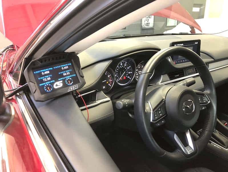
AEM CD-5 Digital Dash
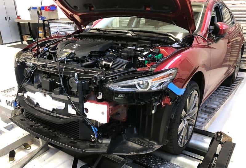
Testing Preparation
To start, we got some new toys from AEM Electronics. The main brain of the entire testing operation for the intercooler is an AEM CD-5L digital dash with logging. This dash allows us to tap into the vehicle’s ECU to see the same information that the OEM sensors are reading. To go along with the CD-5L, we got new AEM sensors that can be positioned to get the data that we need to see how our intercoolers perform.
We used the CD-5 to datalog our dyno runs so we can see what the car is doing while simultaneously seeing power levels from the dyno. To get the data we need, we tapped into the OEM intercooler and 3 intercooler core designs that we created to get pressure and temperature data before and after the intercooler core. In case you were wondering, drilling into a brand new intercooler is stressful!
Once we got everything wired up and the AEM properly set up, we were ready for testing to begin. There were multiple rounds of testing, each consisting of a string of dyno pulls back-to-back to test heat soak. We also performed standalone power runs with the intercooler setups. During testing, we used the full OEM intercooler and piping kit, and each of the CorkSport Intercoolers with the CorkSport piping. Of the three CorkSport intercoolers, we took the best setup and tested it with and without our piping kit.
Conditions were near identical for all tests, with the CS intercooler tests being ~10°F. warmer than the OEM tests (65° vs 55°).
Testing Intercooler Pressure Drop

Starting with pressure drop, the OEM intercooler performed better than we initially expected. The graph above shows the pressure drop across the core through a dyno run. In this case, the smaller the number the better. Starting at around 0.5psi at low RPM and peaking at around 2.4psi at higher RPM is pretty good for a core with fins that are fairly dense.
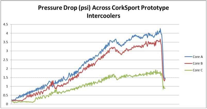
Pressure testing the CorkSport intercooler cores.
Shown in the graph above are the CorkSport intercooler pressure drop results. Core A has the densest fins, while Core C has the least dense fins. Looking at the graph above, you can see that Core A and B had a larger drop in pressure than OEM. Meanwhile, Core C had a smaller pressure drop than the OEM core. Having a smaller pressure drop than OEM means that your turbocharger can make less boost at the turbo yet still hit the boost target in the intake manifold. In other words, your turbo is working less to make the same power levels! Based on our results, option C appears to be the best option due to the low drop in pressure, but first, we will test temperature drop to be certain.
Testing Intercooler Temperature Drop
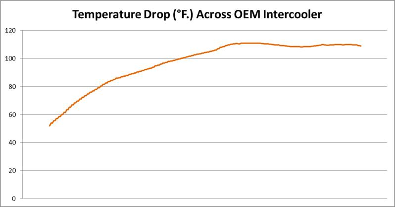
The graph above shows the change in temperature from the inlet to the outlet of the OEM intercooler during a dyno run. As you can see, there is a temperature delta (the amount of heat being removed from the boost air) of approximately 100-110°F through the majority of the dyno run. Not bad for the OEM intercooler as larger the better here, but we can do better.
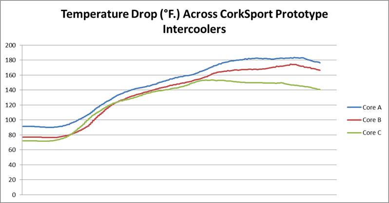
CorkSport Intercoolers Change in Temperature from Inlet to Outlet.
The graph above shows the same temperature drop data for each of the three prototype cores. Please note, the difference at the beginning of the runs is a result of using the run with the best temperature change for each core. With this comparison, larger numbers mean that the intercooler is cooling the boosted air efficiently. As you can see, the very dense cores (A and B) with a high-pressure drop, cool better. However, there are diminishing returns that come when you make a core denser. Through the meat of the dyno run, Core C has approximately 140-150°F of temperature drop, Core A has 150-180°F of temperature drop, and Core B has 140-170°F of temperature drop. This data shows that Core C cools almost as well as A and B despite having a drastically lower pressure drop. Core C is definitely our winner, but we have one last thing to test: heat soak.
Testing Intercooler Heat Soak
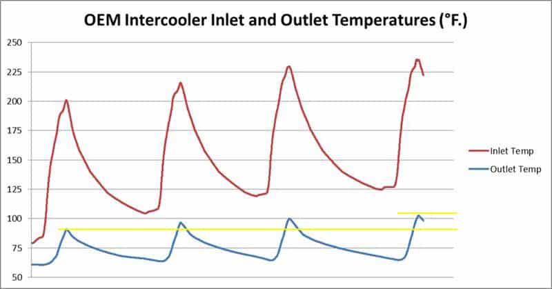
The graph above shows the OEM intercooler tested for heat soak by being run on a dyno in back to back runs. The graph is showing the intercooler inlet and outlet temperatures, so the boost temperature before the intercooler and the boost temperature after the intercooler that your engine sees. Over the runs, the inlet temp increases as the engine and turbo get hot. The OEM core does a pretty good job at preventing the outlet from increasing over the pulls (heat soak), but the CorkSport core can do better.
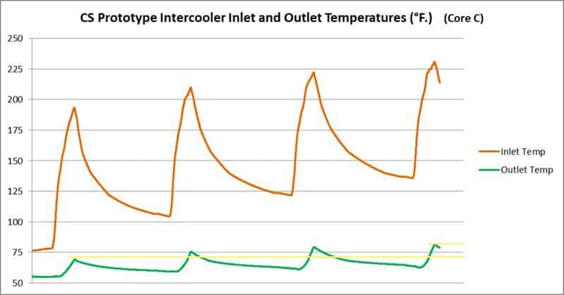
The graph above shows the results of the same test that was performed with the CorkSport prototype Core C. The inlet temp follows a similar path of heating up drastically as the run’s progress, but the improved cooling efficiency is highlighted when you look at the outlet temps. The CorkSport intercooler core cools better and also shows less heat soak, leaving you with 20+ degree cooler temps after the same tests. During testing of the CorkSport core, ambient temps were slightly higher than the OEM test, having been done on a relatively cool day in the mid to upper 50s. If the tests had been performed at 100% identical ambient temps or overall higher ambient temps, the results would be further skewed in the CorkSport kit’s favor!
Testing Intercooler Power
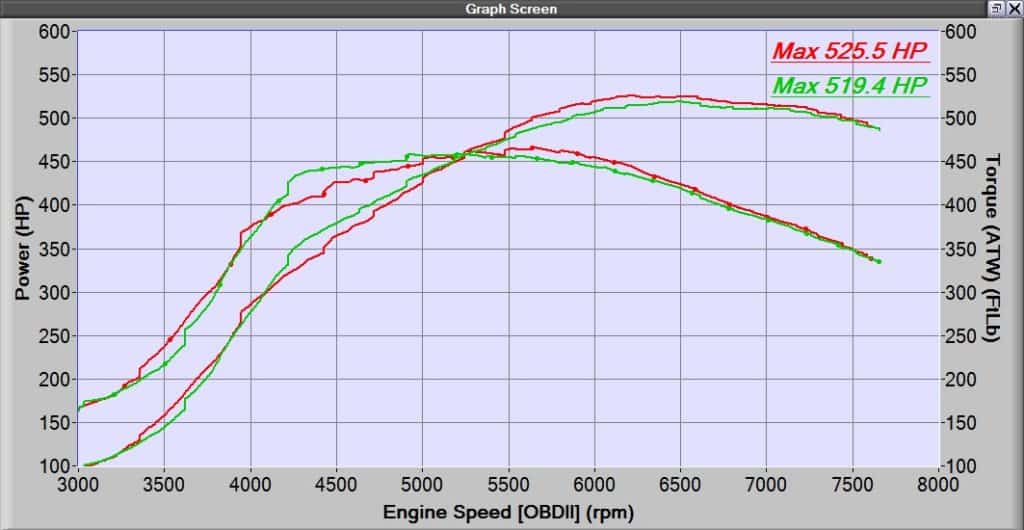
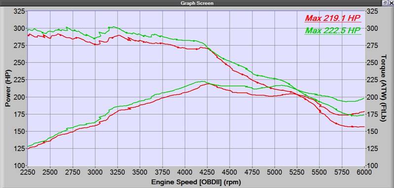
Last, but certainly not least, is power. We tested back to back with the OEM setup, CS FMIC only, and then the CS FMIC with the full piping kit. With the CorkSport FMIC alone, we picked up 3WHP at peak but more importantly, 3-9WHP and 3-12WTQ from 2250-4250RPM. Seen in the graph below.
With the CS intercooler and piping Kit, we picked up around 6WHP at peak compared to full OEM but even more WHP and WTQ through the midrange. For clarity, the graph below is the full CS setup vs. full OEM setup; without tuning!
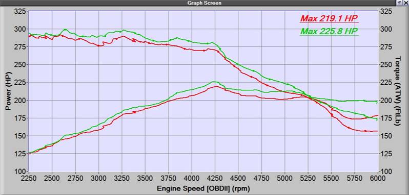
Dyno Testing OEM Intercooler and CorkSport Intercooler with Upgraded Piping
While these gains are decent, the intercooler and piping kit will truly shine once we are able to tune the car for different boost and load targets. In addition, we checked for changes to spool time and throttle response with the piping kit but only noticed marginal gains as we are limited by the current tune on the car. Based on our testing though, it is clear that we are increasing the efficiency of the turbocharging and the intercooling system, which future proofs your ride for further mods and tuning down the road.
Let us know if you have any questions regarding our testing, we can’t wait for you all to get these parts. Look for the CorkSport Intercooler Upgrade and CS Piping Kit coming soon, along with more fun parts for the 2.5T!
-Daniel