Testing – CorkSport External Wastegate Housing for Mazdaspeed

Turbo EWG

Why EWG?  (it’s just about awesome turbo noises)

We hear this alot as the Mazdaspeed platform continues to grow and the 450-500whp build becomes the status quo. Following up the EWG Housing Design & Details Blog about the new CorkSport EWG Housing, we want to share some testing data and differences we saw between an IWG (internal wastegate) and EWG (external wastegate) setups.  

Details about design, flow, placement, data, and feedback from our CST4 EWG Beta Tester.  

IWG vs EWG comparison on the CST4
IWG vs. EWG on the CST4

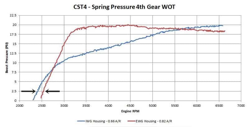
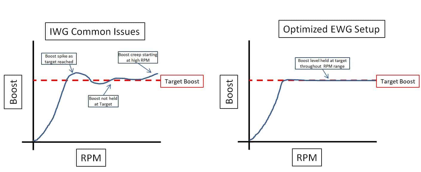
Let’s jump right in!  First up is a spring pressure comparison between the IWG and EWG housing on a CST4 turbocharger.  Let’s first define what “spring” pressure is: this is the resulting boost pressure with 0 added wastegate duty cycle.  AKA we are not trying to add boost pressure.

Immediately you can see some very obvious differences.   The IWG setup has a taper up boost curve that could be considered boost creep.  Some boost creep is ok, but an excessive amount may reach the capacity of the fuel system or other systems in the vehicle.  In this setup that is not the case, but it does show that the IWG is at its limits for boost control.

With the EWG setup you see a much different curve.  The boost builds a few hundred RPM later (due to the larger 0.82 A/R) then climbs right to the spring pressure and then settles to a consistent plateau; very predictable and controllable.  

CAD EWG and IWG Designs
CorkSport EWG and IWG Designs

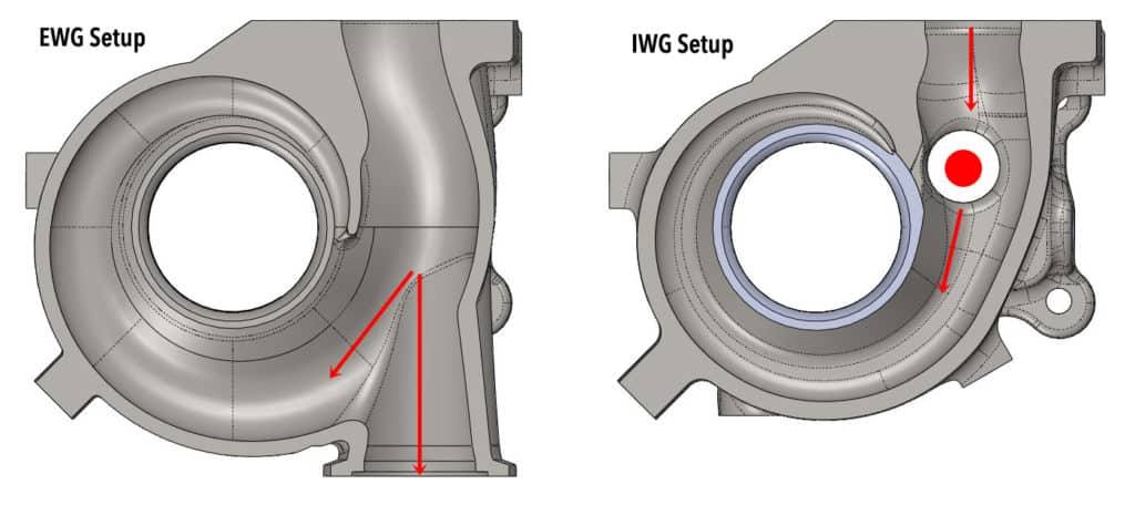
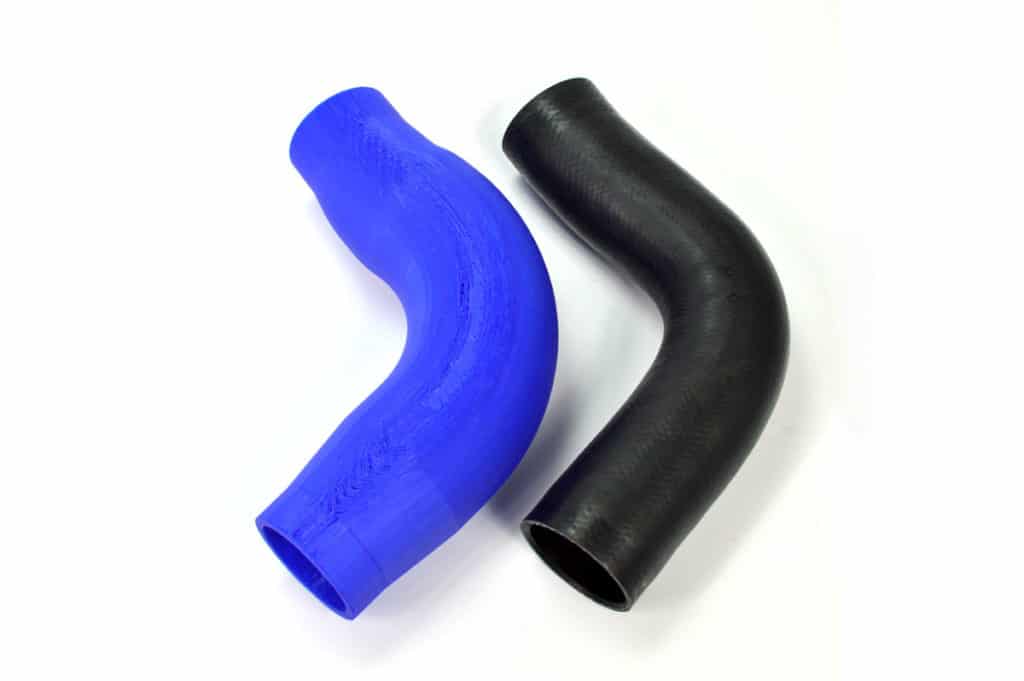
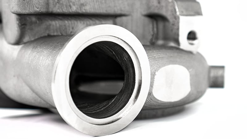
Now let’s look at the design to better understand why.  On the left is the EWG turbine housing with a 0.82 A/R and on the right is the IWG turbine housing also with a 0.82 A/R (we don’t want the A/R to be a factor in this review).   

The EWG housing has a very efficient flow path for the exhaust gas to reach the EWG control valve along with a much larger path to flow.  Both of these features provide excellent flow and thus control of boost pressure.

The IWG housing uses a side port in the turbine scroll to exhaust gas.  In this setup, the exhaust gas must make an abrupt turn and pass through a much smaller port.  Both of these issues reduce boost control.

EWG and IWG Explained

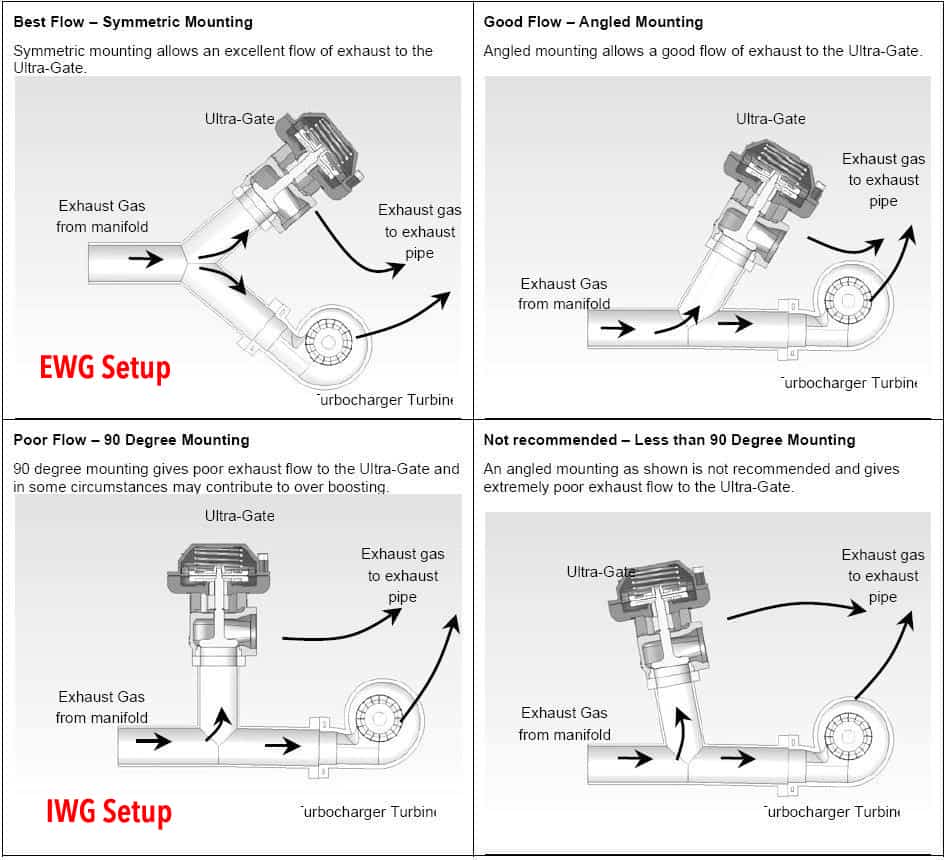
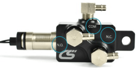
Here is a diagram showing placement of an EWG in the exhaust pre-turbine.  Granted we are comparing a EWG and IWG, but the concept of flow is the same.  

Exhaust gases will always take the path of least resistance and if the turbine wheel is the easier path than the wastegate then boost control will be more difficult.  

Internal and External Wastegate performance chart
(Left) Internal Wastegate Setup | Common Issues
(Right) External Wastegate Setup | Optimized Setup
Click to Expand

This graph was shown in the last blog, but we want to show it again so you can directly compare it to the data graph below.  

Below is the boost curves for the CST5 in both IWG and EWG setup.  Alone each graph actually looks really good, but when overlaid you can see some interesting differences.  

CST5 Dyno testing with IWG and EQG setup

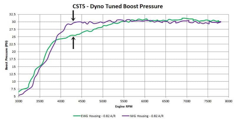
IWG vs. EWG on the CST5

The purple IWG graph has a crisp spool and then flat-lines at approximately 30psi with a slight fall off at 6500rpm.  The CST5 IWG setup does control boost really well, but holding the turbo back at spool up and not over-boosting or spiking was a small challenge.  An abrupt boost curve like this can make the car somewhat difficult to drive because the torque “hits” very hard and you lose traction.

The EWG setup was a bit more controllable.  Not only did the CST5 Mazdaspeed turbo spool a bit sooner, but we were able to better control the spool up boost curve so we could create a torque curve that was more friendly to the FWD traction.  This makes the car more fun to drive. Looking at the higher RPM range we were also able to hold boost more consistently to 7500rpm.

CorkSport External Wastegate

We hope you guys and gals are as excited for the EWG options for the CST4, CST5 and CST6.  They really are an awesome setup for any driving style and power goal.  

Thanks for tuning in with CorkSport Performance.

-Barett @ CorkSport

CorkSport Mazda6 2.5T Boost Tube

We are proud to release the CorkSport Upgraded Boost Tube for 2018+ Mazda 6 2.5T and 2016+ CX-9 2.5T. The CorkSport boost tube is larger, stronger, more reliable, and of course better looking than the OEM rubber tube. Increase throttle response down low, hit boost targets easier and future-proof your ride for mods down the road with a simple 1-hour install. Read on for full details and be sure to check out the R&D blogs here and here for the backstory.

In case you haven’t read the previous blog installments, the CorkSport Boost Tube improves on the OEM boost tube by first strengthening the tube. Instead of using rubber with one reinforcement layer, the CS boost tube use silicone with 5 layers of reinforcement. Aside from the extra layers of reinforcement, silicone stays strong at high engine bay temperatures that may cause rubber to flex excessively. In addition, silicone lasts longer and will better resist cracking as your Mazda 6 Turbo ages. The OEM boost tube is made from materials very similar to the OEM Mazdaspeed 3 boost tubes that showed signs from aging extremely quickly, especially when subjected to higher than OEM boost levels. Cracking or splitting of the OEM tubes results in boost leaks and a poorly running car, definitely not what you want from your brand new SkyActiv 2.5T.

The added strength prevents the CorkSport Upgraded Boost Tube from expanding excessively when subjected to pressure. When pressure tested at 20psi (the largest pressure we have seen at the intercooler outlet), the OEM tube was shown to expand 12% at the internal cross-sectional area. The CS tube tested under the same conditions expanded 3x LESS. This difference would get even larger when subjected to the same pressure at a higher temperature. What does this mean for performance though? When you get on the gas, the boosted air will have to expand the tube before it can enter your engine. The less the tube expands, the easier it is to hit boost targets, and the better throttle response you have, especially down low in the RPM range.

The CS Boost Tube also is a larger inside diameter than your OEM tube. It is 3” through the middle vs. the OEM ~2.44”. Since this area of the charge piping system is directly ahead of the throttle body, this large volume of air has the same effect as it does with our GEN2 Mazdaspeed3 FMIC kit, reducing boost lag and increasing throttle response. For full info on why this happens, check out the release blog for that kit here. As a basic overview, the large volume of air right before the throttle body fools the engine into thinking it has a larger intake manifold plenum than it really does. While not as severe of an effect with just changing this boost tube, try it for yourself and see what you think!

Installing the boost tube is a little tricky due to where it is located, but we include high-quality installation instructions to make it easier. Even so, it can be installed in an hour or less in most cases. We also include polished stainless steel T-bolt clamps to ensure a complete seal and add a subtle visual boost.

Be sure to check out the product listing for more pictures, the installation instructions, and a detailed product video. Let us know if you have any questions, we’ll be sure to help you any way we can!


Lastly, if any of you are looking for a more serious upgrade, stay patient, our FMIC upgrade & full piping upgrade kit are coming soon!

Stay up-to-date on the latest news and product updates from CorkSport.

* indicates required

An Inside Look at the CorkSport EBCS

We recently came across one of the original CorkSport EBCS prototypes which gave us a perfect opportunity to break it down and give you all an in-depth look. Read on as I go through what makes the CS EBCS tick, and more importantly how it gives you great boost control on your Mazdaspeed.

Just as a refresher before we dive in, an electronic boost control solenoid (EBCS) allows for precise boost control by using an electric solenoid to help control the wastegate. A boost reference travels to the EBCS where it can either push on the wastegate diaphragm or vent to the turbo inlet pipe. Where the air travels is controlled by the solenoid.

Obviously, the specifics change slightly depending on a number of factors with the turbocharger setup, but the concepts remain similar. Since the solenoid is electronic, it can be controlled within a tune. This means you are not wholly controlling your maximum boost with the spring in the wastegate and can hit boost targets larger than the “10psi” spring in your wastegate. For more information on boost control and the different EBCS setups, checkout Barett’s white paper on the subject.

Now the above image is a little different from the way you are usually seeing the CS EBCS. Not only is it missing the sweet black anodized finish (early prototype remember?), it needs some assembly before it can function properly. Below lists the components in the system and a short description of what they do. Obviously, we are missing a few key o-rings to keep everything nice and sealed, but all the important bits are there.

  • Manifold: This is the air distribution block. Air/boost comes in one port and leaves through a different port. Where the air goes is determined by the bullet valve.

  • Bullet Valve Assembly: More on this later, but essentially the center rod (piston) moves in and out while the black portion prevents air from reaching one of the manifold ports as needed.

  • Tension Spring: Keeps the bullet valve in the correct position when the system is not energized.

  • Coil Seat: Ensures the copper coil stays in place so the valve can operate properly.

  • Coil/Windings: Creates a magnetic field when energized that moves center rod of bullet valve.

  • Solenoid Body & Wiring: Contains the coil and other components. Also attaches the valve to the manifold.

Each one of the “thirds” of the bullet valve corresponds to one port on the EBCS manifold. They are labeled accordingly above. As EBCS is energized, the piston of the valve is pulled by the magnetic field created by the windings. There is a small amount of movement; only about 12 thousandths of an inch (0.012”) to be exact, which is enough to allow air to either reach the wastegate diaphragm or pass by into the turbo inlet pipe. Again this is simplified as it does not touch on duty cycle-the valve is typically rapidly opening and closing (seriously, check out the white paper).

The bullet valve is advanced technology that offers the utmost in fast responding fluid control. In addition, its profile offers the ability to make a pressure balanced valve and have a manifold that fits just about anywhere. All of this tech means you end up making boost faster, minimizing boost spikes, and keeping boost creep in check. If you want the best in boost control for your Mazdaspeed, be sure to pick up a CorkSport EBCS.

2018 Mazda 6 Performance Parts – Cold Side Boost Tube

You have probably heard us mention the new Turbocharger Mazda 6 in recent weeks and months and have probably been wondering; “what’s going on?”  Well, today we’d like to share a little bit about what’s been going on at CorkSport HQ with our very own 2018 Mazda 6.

Right off the bat, I can say we have a handful of exciting performance products in the works and will be sharing info on them as we make progress.  Today we want to talk about the intercooler piping, specifically the cold side piping and the parts of the system. This is the piping that connects the outlet of the intercooler and the throttle body.  It is commonly referenced as the “cold side piping” because the charge (boosted) air has passed through the intercooler and is therefore cooler.

The OE cold side piping consists of three main components.  Starting on the right side of the image; we have the hard piping that connects to the intercooler and a soft rubber hose.  Next is the soft rubber hose itself, which we will talk more about later. Lastly is the throttle body connection, which is the oddest part of this system.  You can see why in the next image.

The above-mentioned intercooler hard pipe and the rubber hose are pretty common parts on modern turbocharged vehicles, but the throttle body connection is unusual from our experience.  The throttle body connection appears to be designed for a quick connection (and not-so-quick disconnection) during the vehicle assembly process. Unfortunately, this leaves a very odd connection flange on the throttle body itself.  Lastly are the fins inside the connection part; other than straightening the airflow entering the throttle body we don’t see many purposes these. We will be testing the effects and need for these in the near future.

Now let’s get to what we really wanted to talk about; BIG Silicone Performance Parts.

Mazda designed the Turbocharged 2.5L SkyActiv-G to function at a specified boost pressure and no more.  However, we fully intend to change this set boost pressure for increased smiles per gallon. With increased boost pressure comes more force and strain on the OE rubber hose.  Eventually, the OE rubber hose becomes too flimsy for the increased boost pressure and may expand or fail completely via a rupture.

So how do we develop a performance part to replace a rubber hose?  Well, there is one obvious improvement and another not-so-obvious change that can be made.  First, we use silicone as the prominent material for its excellent heat resistance and durability.  Next, the silicone is reinforced with five layers of fabric braiding to withstand the increased boost pressures.  Compare this to the OE single layer of reinforcement and you can see why this would make a big difference.

Now for the less obvious performance improvement; the CorkSport 3D Printed prototype is larger in diameter than the OE rubber hose.  Leaning on our experience with past intercooler piping development, we have found that increasing the charge air volume directly in front of the throttle body increases throttle response and helps spool the turbo faster, reducing turbo lag.  

Currently, we are still in the development phase but will be testing soon.  Stay tuned for future updates on the CorkSport Performance Boost Tube and other exciting products for your 2018 Mazda 6.  

-Barett @ CS

Connect with us:

Stay up-to-date on the latest news and product updates from CorkSport.

* indicates required

You may also like:

Troubleshooting Issues with Your Mazdaspeed Boost Control Solenoid

Having trouble with your mazdaspeed EBCS? Here are the most likely issues and how to fix them.

Good day fellow boosted enthusiast, Vincent here with CorkSport Mazda Performance. Today, I want to share some expert advice with you on diagnosing boost control issues with your turbocharged Mazdas.

I’d venture to guess that about once or twice a week, my team and I get a phone call related to customers that are trying to diagnose a boost control issue with their electronic boost control solenoids (EBCS). Whether it’s too much boost, not enough boost, or random and sporadic boost signals, a boost control issue can have you digging around your engine bay for quite some time if you don’t have a good diagnostic procedure.

This blog is intended to function as an aid in diagnosing boost control issues. If you’re interested in a more thorough understanding of how an EBCS works, check out this white paper that one of our engineers wrote. Now let’s get to it!

What An EBCS Is and Is Not

The EBCS is a unit composed of an electrically operated solenoid housed in its own little manifold designed to regulate and route boost signals to the appropriate area in the engine bay. The EBCS is not the mechanical device that physically moves the wastegate flapper to re-route exhaust gases around the turbine wheel, that’s the job of the wastegate actuator.

Now that we cleared that up, let’s look into some possible causes for poor boost control issues.

Hoses

I can’t stress this one enough. I would say a bad or improperly routed vacuum hose is the root cause for about 70% of all issues. When diagnosing a boost control issue, start with a visual inspection of all vacuum hoses in the system. Any hoses with nicks, tears, rips, or cuts should be replaced with a good quality silicone vacuum hose. Silicone is preferred because it has a longer life than a traditional rubber hose and tolerates engine bay heat better. Also, check to make sure the hoses are not pinched in between anything. I’ve seen cases where a signal hose gets trapped between a nut and stud of some sort, causing it to be completely pinched off and rendering it useless. So make sure your hoses go from point A to point B clearly and perfectly with no stops.

Boost Tube

Routing

Since we’re on the subject of hoses, let’s also be sure that we’re routing them correctly. Each hose is meant to take some air from one place to another in a particular fashion. Often times guys and gals get in a rush and just start plugging in hoses wherever they see empty spots. This is especially evident on the EBCS unit itself considering there are 3 ports on it that are all very close to each other and it’s quite easy to put the wrong hose on the incorrect port. This is where a good set of high-quality instructions becomes helpful, so you always have something to reference.

Important note: Make sure to reference instructions specific to the brand of EBCS your vehicle is equipped with, not all controllers designate the same letters and ports.

CorkSport EBCS
CorkSport EBCS

Isolating The Problem

If you’re dead certain that the above two points check out, then the next logical step is to isolate the problem. What I recommend is to set your turbocharger to run off of spring pressure only. What you would be doing here is run a hose from the compressor cover to the lower nipple on the wastegate actuator (WGA) and then put a vacuum cap on the other port of the WGA. When this is done, what you’re doing is isolating the mechanical side from the electrical side.

If we perform this and our car runs 100% hitting the targeted spring pressures, then we can check off the turbo or WGA as being the issue and we can return our focus to the solenoid and its components. If we’re in this set-up and still experiencing a boost control issue, then we want to check out the turbo and its related components. Things to check are the WGA flapper for any binding or contact, and the turbocharger itself for any mechanical issue such has damaged wheels or housings. Also, we want to check any boost tubes, intercooler piping, connections, etc. to make sure it’s not skewing any of our signals.

Fixing The Problem

If you get to the point where you feel the EBCS unit itself is the problem, a simple thing to do (if you have the ability to) is to bug a friend. Say your buddy is running the exact same EBCS as you, ask him to borrow it for half an hour and swap it in. If we leave everything as we had it and swap solenoids, and our problem goes away then we have a really strong reason to believe the controller is the issue and it should be inspected. This is the point when you would want to contact the manufacturer so you can send it to them and have them test it. Don’t try to take it apart yourself! Almost all solenoids have really tiny and precise O-rings that can break easily if mishandled.

These are just some of the most obvious and most likely things to check. Before going too crazy, you still want to be sure that you have a healthy engine and no other forced induction problems such as a massive boost leak somewhere that can skew results.

I hope this blog was helpful and can be useful to some of you. I leave you with some last minute points.

  • When diagnosing, change one thing at a time to eliminate variables. You don’t want to jump in and change 10 different things and hope for the best. You’ll just waste time and resources.
  • Double-check your tune. When switching to an aftermarket EBCS, a tune will be required since almost all aftermarket units work faster and are much more precise than an OEM unit.
  • In regards to vacuum hose length, I can say for 99% of you it won’t matter. Unless you’re running 20+ feet of hose, the length will not affect your signals. At the tiny sizes we’re using, you’ll need lots of hose for length to make any noticeable impact. My recommendation is to use just what you need for a nice clean set up, no more and no less.

Connect with us

Stay up-to-date on the latest news and product updates from CorkSport.

* indicates required

You may also like